Text in blue Italics is derived from the AS/NZS ISO/IEC 14763-3:2017 standard
1. Applicability
The following applies to optical fibre permanent link and link testing of cabling installations seeking performance conformance to AS/NZS 11801.1 using AS/NZS 14763.3:2017 light source and power meter (LSPM) testing methods.
2. Background
The test configuration reference planes of a link and permanent link contain the connecting components at both ends and all the cable and components between the end components.
For links and permanent links, either the One-Test-Cord Reference Method or the Enhanced Three-Test-Cord Reference Method may be used. Both these reference methods include the contribution of the end connectors and both meet AS/NZS 14763.3 requirements.
Note: The previous Three-Test-Cord Reference Method has been removed from the Standard.
The Enhanced Three-Test-Cord Reference Method is suitable for mismatched connector Links and Permanent Links.
3. Link definition
A ‘Link’ is any fibre transmission path between two cabling system interfaces, including the mated connections at each end. A ‘Permanent Link’ is any fibre transmission path with mated connections at each end that runs from FD to TO. (AS/NZS 14763.3:2017 Appn ZZ1 a and b)
Hereinafter the word ‘Link’ is used to collectively describe both a permanent link and a link.
4. Bi-directional Testing
For Australia and New Zealand, unless states otherwise in the Quality Plan;
Testing of links with light source and power meter shall be bi-directional and at least at two appropriate wavelengths, (Appn ZZ2 Cl 9.1.1.4 of AS/NZS 14763.3:2017)
For bi-directional testing using LSPM, the worst one of the two measured results shall be considered as the overall measured result.
5. Test Cords
Both multimode and singlemode fibre reference setting should for most applications use the following test cords;
- · LTC Launch Test Cord (2 – 10 m with reference connector at link interface end)
· STC Substitution Test Cord (2 – 10 m with reference connector at link interface end)
· TTC Tail Test Cord (2 – 10 m with reference connector at link interface end)
The LTC for multimode fibres shall meet the launch modal distribution condition at the output of the launch test cord to meet Encircled Flux (EF) requirements.
The LTC for singlemode fibre meets its launch condition through the test instrument. Alternatively, the singlemode LTC shall contain a minimum of two single air-coiled turns or mandrel wraps of 35 to 50 mm diameter.
The LTC, STC and TTC for multimode and singlemode must have a connector end face that will mate with the link connectors.
All connectors shall be inspected and cleaned as necessary before reference setting and should be inspected before each individual test.
6. One-Test-Cord Reference Method for LINK ATTENUATION
(Note: Channel testing used a differentreference method)
6.1. Allow the light source to warm up following the tester manufacturer's recommendations. This could take up to several minutes.
6.2. Connect the LTC to the light source at one end and to the power meter at the other end. Ensure EF compliance of the LTC for multimode fibre.

6.3. Set the reference to 0.0 dB or record the reference power in dBm or watts.
6.4. The attenuation of the connectors on the launch test cord and tail test cord should be verified by connecting these cords together and verifying the attenuation of this connection is no more than the expected attenuation between two reference grade connectors.

Disconnect the LTC from the power meter and connect it to the TTC using a Reference Adaptor. Connect the other end of the TTC to the power meter.
The attenuation of the reference-to-reference connection must be no greater than;
MMF 0.1 dB, SMF 0.2 dB.
Note: If the attenuation is more than the allowable value, clean all end faces, inspect then reconnect and re-test. Re-set the reference if necessary. Use alrenate test cords if necessary.
Disconnect the LTC from the TTC at the reference adaptor but do not disconnect the other ends from the light source or power meter; otherwise re-set the reference as per Item 6.2.
6.5. Connect the LTC to the cleaned fibre connector at the Near End of the link.
At the far end, connect the TTC to the cleaned connector of the link.

6.6. Measure the attenuation of the link, which includes the two end connectors.
6.7. During testing, to improve test result reliability and accuracy and to reduce measurement uncertainty, the attenuation of the connectors on the launch test cord and tail test cord should be verified from time to time by connecting these cords together and verifying that the attenuation of this connection is still no more than the expected attenuation between two reference grade connectors. This is a repeat of the measurement in Item 6.4.
7. Enhanced Three-Test-Cord Reference Method for Link Attenuation
(Note: Channel testing uses a different reference method)
The test meters and test cords must be capable of accepting different adaptors if different connectors are involved on the link under test.
7.1. Allow time for light source stabilisation following the manufacturer’s recommendations. This could take several minutes.
-
- Connect the LTC to the light source at one end and to the power meter at the other end. Ensure Encircled Flux compliance of the LTC for multimode.
7.3. Set the reference to 0.00 dB or record the reference power in dBm or watts.
-
- Connect the STC and TTC using reference adaptors between the LTC and power meter.

-
- 7.5. Measure and record the attenuation or power of the three test cords.
- The attenuation of the two reference-to-reference connections must be no greater than;
MMF 0.2 dB, SMF 0.4 dB.
Note: If the attenuation is more than the allowable value, clean all end faces, inspect then reconnect and re-test. Re-set the reference if necessary. Use alrenate test cords if necessary.
This step enhances the accuracy and reduces the uncertainty of the final test result. Hence the name Enhanced Three-Test-Cord Reference.
7.6. Remove the STC and reference adaptors; connect the LTC and TTC to the link under test.
Do not remove test cords from the testers; otherwise re-set the reference as per Item 7.2
7.7. Measure and record the attenuation of the link, which includes the two end connections.
7.8 During testing, it is strongly recommended that the LTC, STC and TTC be connected together on occasions to ensure the value is still below the maximum allowed in Item 7.5.
8. Treatment of Link Test Results
Using the One-Test-Cord Reference Method or the Three-Test-Cord Reference Method, the PASS limit for link attenuation is;
MMF Limit = (2 x 0.5 dB) + Σ (cable attenuation) + Σ (embedded connector attenuation)
SMF Limit = (2 x 0.75 dB) + Σ (cable attenuation) + Σ (embedded connector attenuation) (Clause 9.1.1.8 of ASNZS 14763.3:2017 Corrigendum 1)
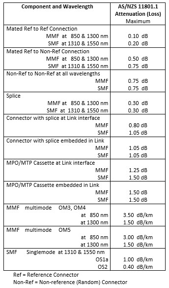
Table 6 Allowable Attenuation Values
9. Apparent Gains
Apparent gains shall not exceed the measurement uncertainty. (AS/NZS 14763.3:2017 Appendix ZZ2 Clause 5.3.5)
10. Measurement Uncertainty
Measurement uncertainty (for testing links) is the same for both the one-test-cord reference and the enhanced three-test-cord reference methods. (AS/NZS 14763.3:2017 Annex E.1)
- Measurement uncertainty for all Link testing;
- SMF is ± 0.24 dB
MMF is ± 0.27 dB when attenuation is ≤1.9 dB
MMF is ± (0.14 x attenuation) when attenuation is >1.9 (AS/NZS 14763.3:2017 Appndix ZZ2 E.2.2 h and E.3.2 g)
11. Mated Connections in Close Proximity
Each MPO cassette shall be considered as two mated connector interfaces when determining optical attenuation budget. Also, connectors containing a mechanical or fusion splice with a pre-polished stub are deemed to be a connector and a splice for loss budget calculations. (AS/NZS 14763.3:2017 Appendix ZZ2 Clause 9.1.1.8)