Text in blue Italics is derived from the standards
1. Applicability
The following applies to optical fibre channel testing of cabling installations seeking performance conformance to AS/NZS 11801.1 using AS/NZS 14763.3: 2017 light source and power meter (LSPM) testing methods.
2. Background
The test configuration reference planes of a channel contains the equipment cords at both ends and all the cable and components between the equipment cords, but not the connectors on the equipment cords that interface to the equipment.
This Technical Note explains how to test an optical fibre channel using the Enhanced Channel Testing procedure to exclude the contribution of the two equipment cord end connectors that connect to the terminal equipment and meet the requirements of AS/NZS 14763.3:2017.
3. Bi-directional Testing of Channel
Unless stated otherwise in the Quality Plan; testing of a channel with light source and power meter should be in both directions and at two appropriate wavelengths, with the worst one of the two measured results taken as the overall measured result.
4. Test Cords
For both multimode and singlemode fibre, the method of reference setting uses the following cords for testing;
- LTC Launch Test Cord (2 - 10 m long; with reference connector at Channel interface end)
- NEC Near-end Equipment Cord (the customer's near-end equipment cord at the light source)
- FEC Far-end Equipment Cord (the customer's far-end equipment cord at the power meter)
Note: The customer's far-end equipment/patch cord FEC (at the other end of the channel i.e. the power meter end) is not used during reference setting but it is used during the channel test.
The LTC for multimode channels shall meet the launch modal distribution condition at the output of the launch test cord to meet Encircled Flux (EF) requirements. The LTC for singlemode fibre typically meets its launch condition through the test instrument. Alternatively, the singlemode LTC shall contain a minimum of two single air-coiled turns or mandrel wraps of 35 to 50 mm diameter.
The LTC for multimode and singlemode must have the end face that will mate with the equipment cords. All connectors shall be inspected and cleaned as necessary before reference setting and should be insprcted before each individual test.
The equipment cords NEC and FEC should also have the end face that will mate with the LTC and with the power meter, inspected and cleaned before reference setting and before each individual test.
5. Enhanced Channel Test Reference Method
Clause 9.1.1.2 of AS/NZS 14763.3:2017 sets out the following method, which is a modified version of the one-test-cord method of reference setting, using the customer's equipment cord during reference setting.
5.1. Ensure the launch test cord is qualified/verified as functioning properly.
5.2. Allow the light source to warm up following the tester manufacturer's recommendations. This could take several minutes.
5.3. Connect LTC to the light source at one end and the equipment cord NEC at the other end using a reference adapter. Ensure EF compliance of the LTC for multimode fibre. Connect the other end of the NEC to the power meter.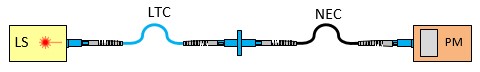
5.4. Set the reference to 0.0 dB or record the reference power in dBm or watts.
5.5. Connect the LTC-NEC combination to the connector on the fixed cable of the channel.
5.6. At the far end of the channel, connect the FEC to the power meter. Then do not disturb the joints between the fixed fibre cable, NEC and FEC as these are part of the channel under test.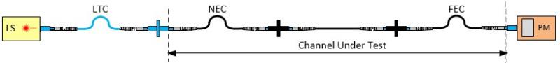
5.7. Measure the attenuation of the fibre Channel, which includes the two customer equipment cords but not the two end connectors.
Note: This enhanced channel test is for the first direction. For the second direction of bi-directional testing, to test from the far end back to original near end, the reference must be re-set using the "LTC-FEC" combination and repeat steps 5.3 to 5.7.
Test Procedure Rational
- By channel definition, the first and last connectors are not part of the channel.
- The first connector on NEC is referenced out during reference setting.
- The last connector on FEC is not measured because it is connected to the power meter.
- This test procedure meets the reference planes in AS/NZS 14763.3 and AS/NZS 11801.1.
- This procedure is called the Enhanced Channel Test for optical fibre in AS/NZS 14763.3.
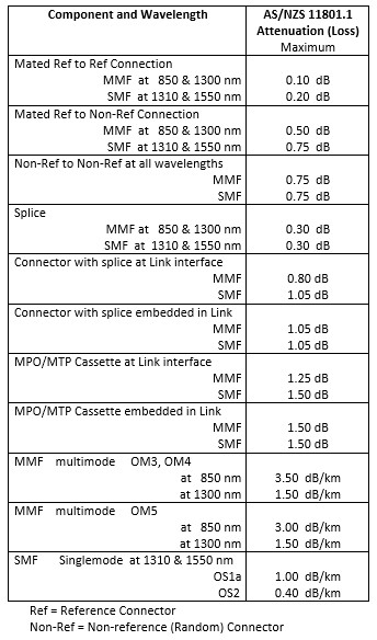
6. Treatment of Channel Test Results
6.1. Using the enhanced channel test reference method the limit of testing for channel attenuation is;
Channel Attenuation Limit = Σ (cable attenuation) +Σ (embedded connector attenuation)
See Table 6 below for component maximum attenuation values.
Example; 100 m channel of OM5 cable with MPO cassettes each end, the attenuation limits are:-
At 850 nm (0.1 x 3.00) + (2 x 0.75) + (2 x 0.75) = 3.30 dB
At 1300 nm (0.1 x 1.50) + (2 x 0.75) + (2 x 0.75) = 3.15 dB
6.2. There is a second and equally important limit that the channel must also pass.
Appendix E.2 of AS/NZS 11801.1 requires that a channel not exceed the maximum attenuation allowable for the customer's intended application.
Example; for 10GBASE-SR, the attenuation limit is:-
2.90 dB @ 850 nm, and not applicable @ 1300 nm.
The channel must pass the lower limit of 6.1 and 6.2.
Example; Max channel attenuation loss limit is 2.90 dB @ 850 nm and 3.15 dB @ 1300 nm.
7. Apparent Gains
Apparent gains shall not exceed the measurement uncertainty (AS/NZS 14763.3:2017 Appendix ZZ2 Clause 5.3.5)
8. MEASUREMENT UNCERTAINTY
- SMF is ± 0.24 dB
- MMF is ± 0.27 dB when attenuation is ≤1.9 dB
- MMF is ± (0.14 x attenuation) when attenuation is >1.9 dB
(AS/NZS 14763.3:2017 Appendix ZZ2 Clause E.2.2 h)
9. Mated Connections in Close Proximity
Each MPO cassette shall be considered as two mated connector interfaces when determining optical attenuation budget. Also, connectors containing a mechanical or fusion splice with a pre-polished stub are deemed to be a connector and a splice for loss budget calculations.
Table 6 Allowable Attenuation Values